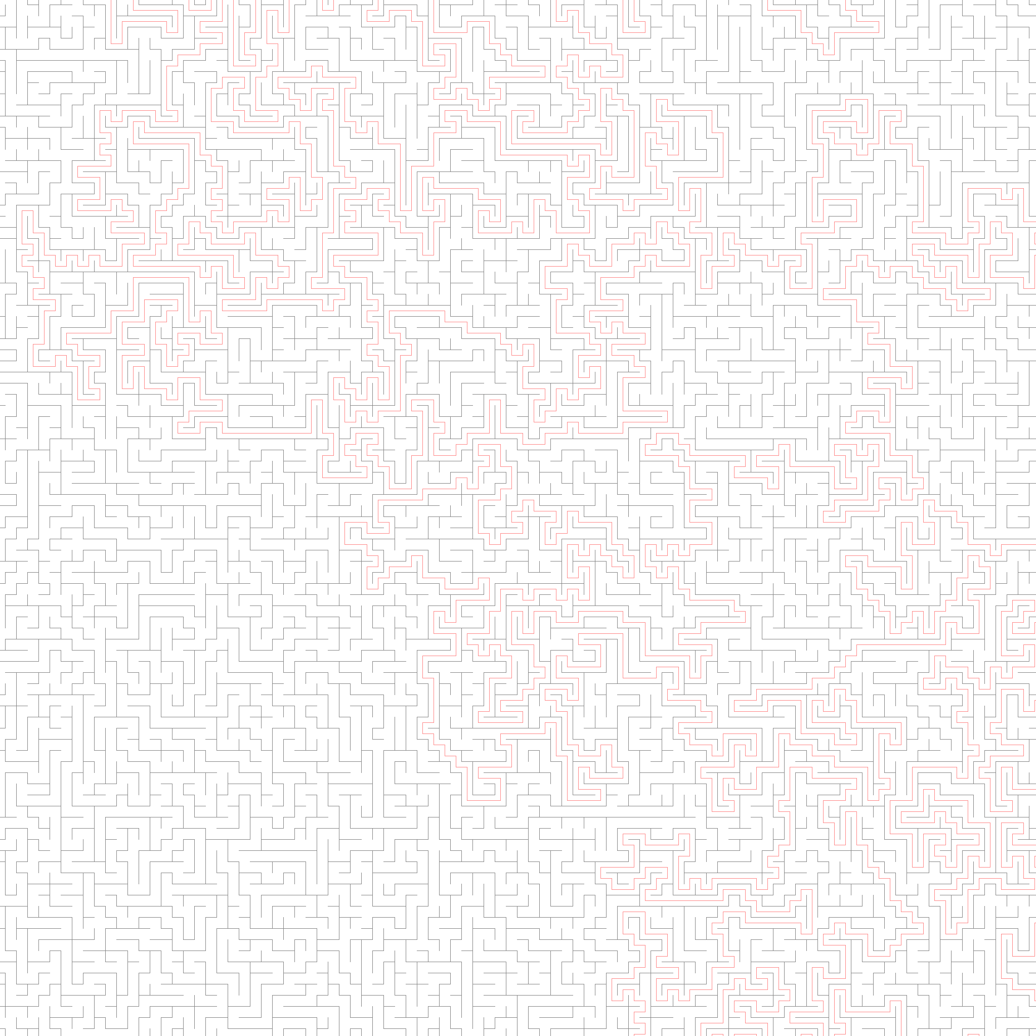
Given an image of a maze, produce another picture with the solution drawn in. That's the challenge my colleagues Jens and Martin recently put to our development team. My first thought was "there must be a way to solve this without 'parsing' the maze out of the image, right?". Turns out there is a way.
Important: License
The images in this article are direct reproductions or derivatives of mazes created by Martin and Jens as part of their activity as employees of MüllerBBM VibroAkustik Systeme (MBBM VAS). They are the property of MBBM VAS and included on this site with permission but MUST NOT be reproduced further without written permission.
Similarly, the algorithm presented here was devised on company time with support from my colleague Philipp, thus the original version is also the property of MBBM VAS. The version shown here is rewritten from scratch on my own time. Nevertheless, please do not copy any of it verbatim, but rather use it as inspiration to come up with a better version.
In other words, the content of this article is an exception to the CC NC SA 4.0 License used for other content on this site.
Now, back to the fun part!
Mazes fall apart
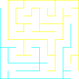
More precisely, when standing at the entrance, the wall to your left and the wall to your right are not connected. So if you could wave a magic wand and colour one wall red and the other blue, you'd only have to make sure to always have a red wall on one side and a blue wall on the other and you'd easily find your way to the other side.
Luckily, image processing gives us such a magic wand and the spells to easily draw a map.
The Algorithm
The following code is extracted from a program that takes the path to the input and desired output location as its first and second arguments. For brevity some code is omitted. You can find the full program on GitHub.
Guarantees made about the input mazes
- Corridors are pure white and have a width of an odd number of pixels
- Width and height of corridors are equal
- Walls are pure black and 1 px wide
- The entire maze is surrounded by a wall
- There is exactly one "entrance"/beginning and it is defined to be in the top left corner
- There is exactly one "exit"/end and it is defined to be in the bottom right corner
Preparing the Ground
To start off, we load the input image and make a copy we can work with.
auto input = vips::VImage::new_from_file (argv[1]);
auto in_copy = input.copy_memory();

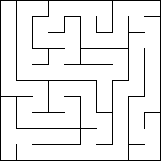
There are a lot of guarantees made about the input to the program, but the width of the corridor is unknown. Therefore, we do have to do a little bit of parsing to find the width of the corridor. We do so by advancing diagonally until we hit upon a black pixel, i.e. a wall.
size_t corridor_width = 0;
while (in_copy(corridor_width + 1, corridor_width + 1)[0] != 0) {
    ++corridor_width;

    if (corridor_width + 2 > in_copy.width()
        || corridor_width + 2 > in_copy.height()) {
        std::cout << "Corridor width seems to be greater than image size "
            "allows. Exiting program.\n";
        return -1;
    }
}

if (corridor_width % 2 == 0) {
    // can't draw a line in the middle of an even-sized corridor
    std::cout << "Corridor width seems to be even. Exiting program.\n";
    return -1;
}
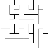
Since the input images in the challenge have a 1 pixel wide frame around their edge which connects the two sets of walls, we need to "cut open" the entrance and exit to the maze.
auto entrance_size = corridor_width + 1;
in_copy.draw_rect({255}, 0, 0, entrance_size, entrance_size,
    vips::VImage::option()->set("fill", true));
in_copy.draw_rect({255}, in_copy.width() - entrance_size, in_copy.height() - entrance_size, entrance_size, entrance_size,
    vips::VImage::option()->set("fill", true));

Finding the two halves
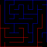
Now that we know what we are working with, we can get on with the magic trick by colouring the two now-disjoint wall sections.
in_copy.draw_flood({255, 255, 0}, entrance_size, 0,
    vips::VImage::option()->set("equal", true));
in_copy.draw_flood({0, 255, 255}, 0, entrance_size,
    vips::VImage::option()->set("equal", true));

In preparation for the next step, we need to invert the image to get zero energy in corridors and single channel energy on walls.
auto inverted = in_copy.invert();

Creating the fine line in the middle
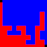
Now all is ready to reveal the path by convolving this image with a rather brute-ish kernel consisting of all ones in a square with a width equal to the corridor width plus two.
For better performance, we use a 1D Kernel and seperable convolution.
Side Note 1
For an in-depth primer on convolution, look no further than this excellent video from 3Blue1Brown.
Side Note 2
is not seperable in the general case since , where are matrices of ones.
However, the particularities of the challenge and the mechanisms of the image processing library (e.g. overflow handling) allow us to get away with this optimisation. Even the 2D kernel would not work without these assumptions.
auto kernel = vips::VImage::new_matrix(corridor_width + 2, 1);
kernel.draw_rect({255}, 0, 0, kernel.width(), kernel.height());
auto convolved = inverted.convsep(kernel);

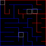
To illustrate what happened, have a look at this image of another maze with the kernel boxes drawn in.

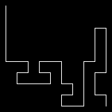
With all irrelevant paths fully filled up and the one correct path defined by the overlap between the red and blue pixels, we can get the path by multiplying those two channels.
auto intersection = convolved[0] * convolved[2];

Final composite
Now all that remains is to colour the path cyan (i.e. "un-red")...
auto cyan_path = extracted.linear({0, 255, 255}, 0);

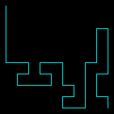
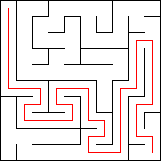
...and to subtract this image from the original input to get the final solution.
// subtract cyan path from the white corridor pixels to get a red trace
auto solved = input - cyan_path;

Credit where it is due
The original challenge required the input to be taken in the form of a HTTP request and the result to be returned as a response. There was also a load-testing part to it.
The whole solution was devised together with my colleague Philipp who did the heavy lifting of making the HTTP Server withstand a deluge of requests while I ironed out the image processing. In the end we met in the middle where we both had to figure out how to stitch a C program with a non-trivial dependency (Vips) together with a Rust program.
As mentioned in the beginning, the authors of the challenge were Jens and Martin who generated the input mazes, created a validation program as well as a load testing routine for the server and did a lovely job moderating the day.

